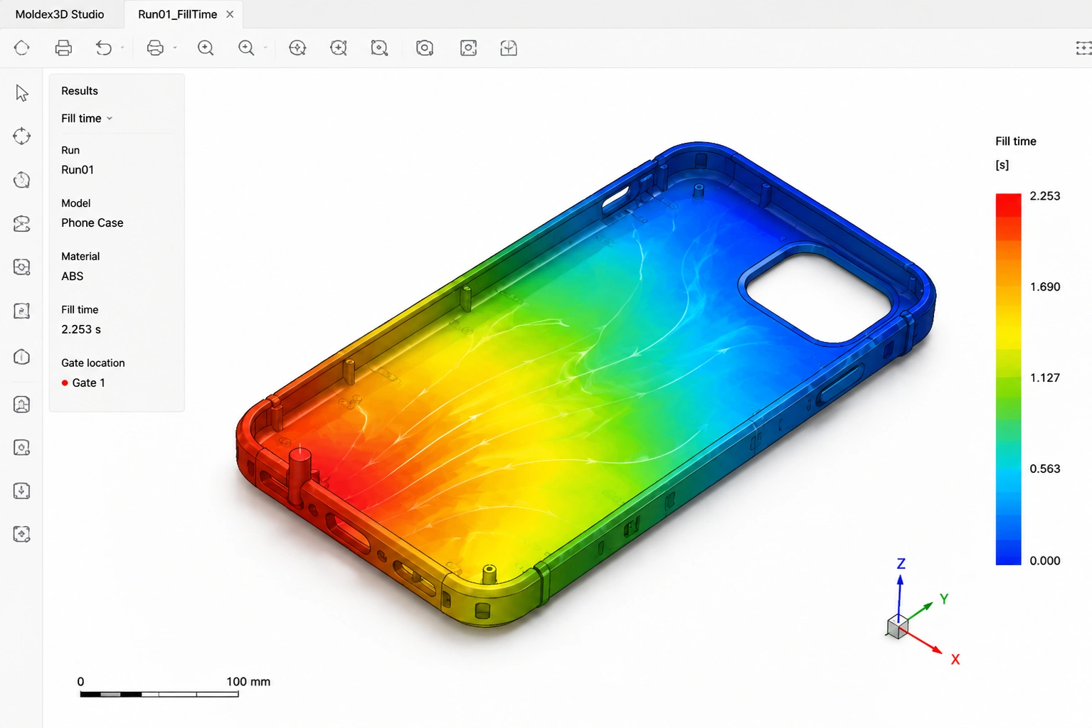
A plastic part may look ready in CAD but still create problems during injection molding. Thin walls, long flow paths, poor gate placement, and uneven cooling can lead to short shots, weld lines, sink marks, or warpage.
Mold flow analysis helps you identify these risks before the mold is manufactured. By simulating how molten plastic fills, packs, and cools inside the cavity, you can make better design and tooling decisions while changes are still relatively easy to implement.
What Is Mold Flow Analysis?
Table of Contents
ToggleMold flow analysis is a computer-based method used to predict how molten plastic will move through an injection mold.
To run an injection molding simulation, you typically need information such as:
- Your part geometry
- The selected plastic material
- Gate and runner locations
- Mold and melt temperatures
- Injection and holding-pressure settings
- Cooling conditions
Depending on the level of analysis, you can evaluate:
- Fill patterns
- Injection pressure
- Short-shot risk
- Weld-line locations
- Air traps
- Gate balance
- Packing and shrinkage
- Cooling performance
- Potential warpage
A basic plastic flow simulation may show whether your cavity is likely to fill. A more detailed plastic injection molding simulation can also help you evaluate packing, cooling, shrinkage, and final part deformation.
However, a mold flow report is not simply a pass-or-fail document. Its value depends on the accuracy of the inputs and how the results are interpreted in relation to your actual mold and production conditions.
What Problems Can the Simulation Identify?
1. Unbalanced Filling and Short Shots
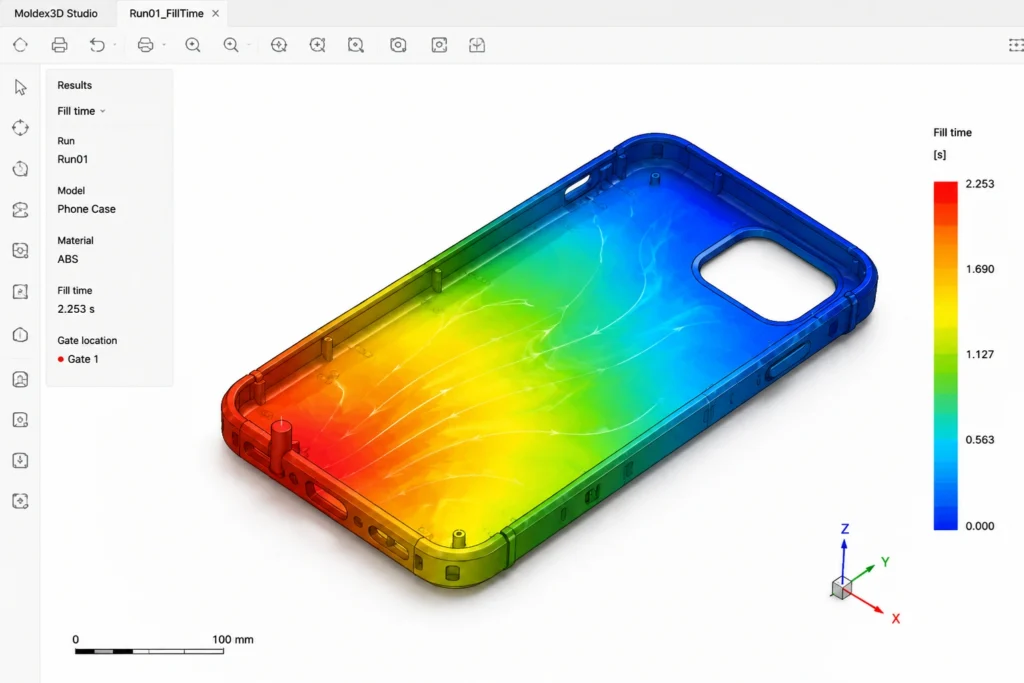
A fill-pattern result shows how molten material travels from the gate into different areas of your cavity.
If your part has thin walls, narrow sections, or a long flow path, the melt may begin to cool before reaching the end of the cavity. This can lead to short shots, incomplete features, or an unstable processing window.
Based on the results, you may need to:
- Adjust local wall thickness
- Create smoother thickness transitions
- Relocate the gate
- Add another gate
- Select a material grade with better flow properties
The goal is not only to determine whether your part can fill once. You also need to know whether it can fill consistently during production.
2. High Injection Pressure and Poor Gate Placement
High injection pressure may indicate that the material is struggling to move through the runner, gate, or cavity.
Common causes include:
- Excessively long flow paths
- Walls that are too thin
- Gates that are too small
- Sudden changes in wall thickness
- Material with insufficient flowability
- Unrealistic process settings
You should not simply aim for the lowest possible pressure. Your target should be a practical molding window that works with your material, mold structure, molding machine, and quality requirements.
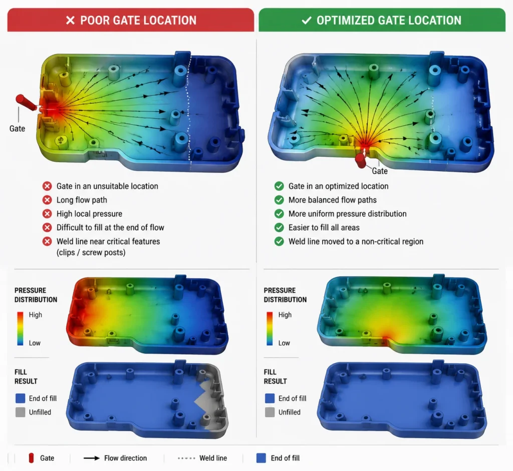
Gate placement also affects more than filling. It can influence:
- Flow balance
- Weld-line locations
- Air traps
- Packing performance
- Gate vestige
- Surface appearance
A gate may fill your part successfully but still create an unacceptable mark on a visible surface. It may also move a weld line toward a snap fit, screw boss, sealing area, or another critical feature.
A useful injection molding analysis therefore considers appearance, structure, and manufacturability together.
3. Weld Lines and Air Traps
Weld lines form when two or more melt fronts meet inside the cavity.
Whether a weld line is acceptable depends on where it appears and how your part will be used. A weld line in a hidden, low-stress area may have little effect. One near a clip, boss, sealing feature, or cosmetic surface may create a structural or visual problem.
With mold flow analysis, you can predict likely weld-line locations before cutting the mold. You may then relocate the gate or modify the geometry to direct the weld line toward a less critical area.
The simulation can also help you identify possible air traps. Trapped air may contribute to:
- Burn marks
- Incomplete filling
- Surface defects
- Weak local areas
- Inconsistent molding results
Knowing where air is likely to collect can help you plan venting before the first mold trial.
4. Shrinkage, Sink Marks, and Warpage
Your part is not finished once the cavity is filled. The material still needs to be packed and cooled.
If wall thickness, packing pressure, or cooling is uneven, you may see:
- Sink marks
- Uneven shrinkage
- Dimensional variation
- Flatness problems
- Warpage
- Inconsistent assembly gaps
These issues are particularly important when your molded part must align with other components. Even relatively small deformation can affect fit, sealing, fastening, or final appearance.
A detailed injection molding simulation allows you to compare how different gates, materials, wall thicknesses, and cooling layouts may affect the final part shape.
Why You Need to Evaluate Material and Geometry Together
Your simulation results are influenced by both the part design and the selected material.
Different plastics behave differently in terms of:
- Melt viscosity
- Flow length
- Shrinkage
- Processing temperature
- Cooling rate
- Fiber orientation
- Thermal properties
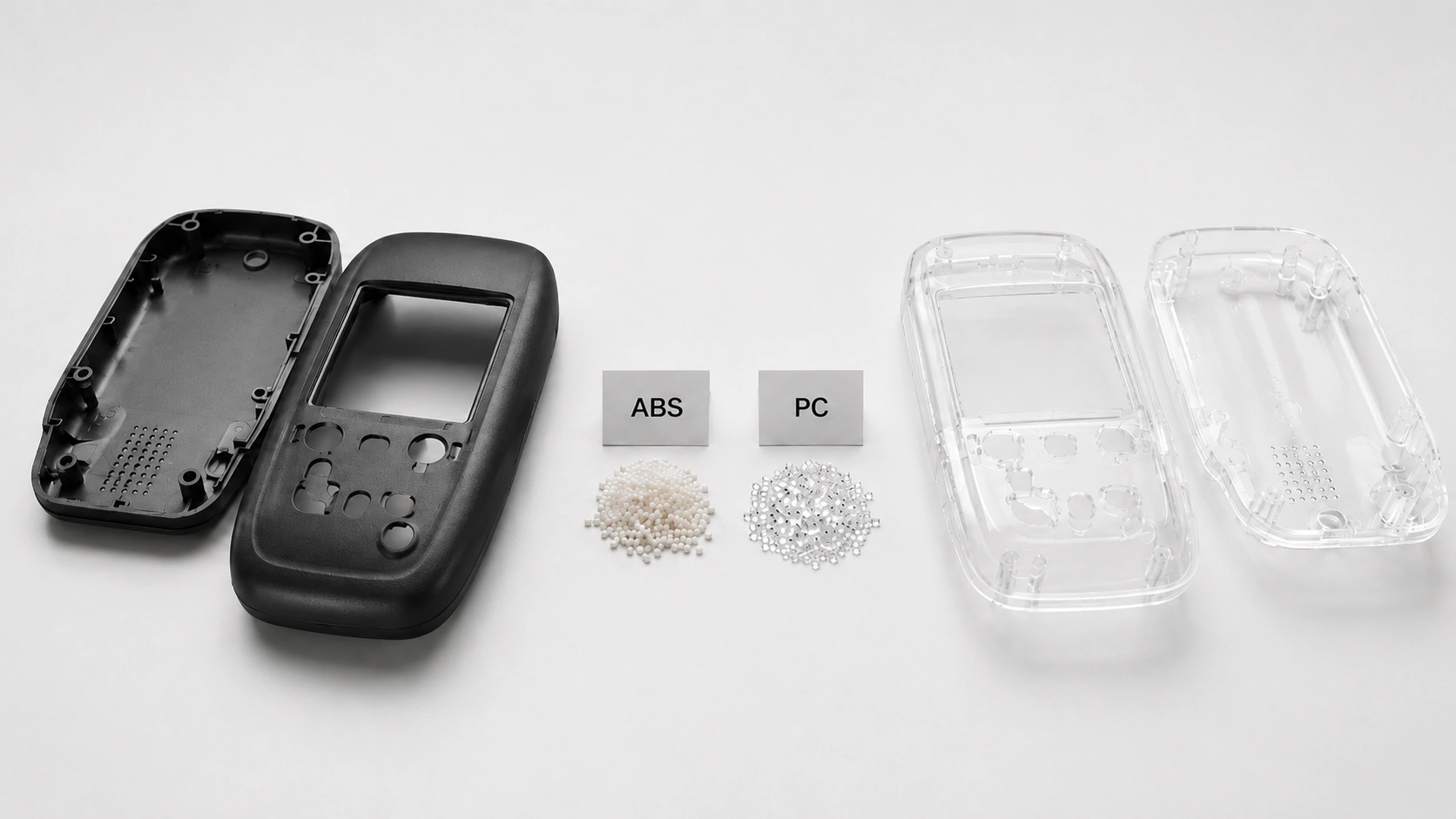
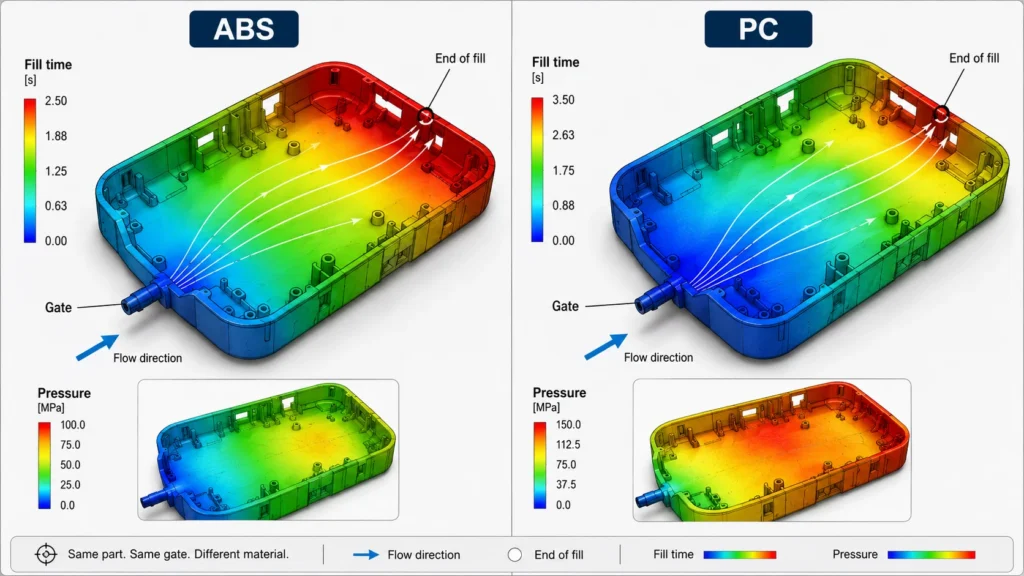
For example, a design that fills relatively easily in ABS may require higher pressure or a different gate arrangement when molded in PC.
If you are comparing these materials for an enclosure or protective component, our ABS vs. polycarbonate guide explains how flow behavior, impact strength, surface requirements, processing conditions, and cost affect the final choice.
Even two grades of the same material can produce different results. One PC grade may flow more easily than another, while one ABS grade may have a different shrinkage rate.
For a reliable plastic mold flow analysis, you should use material data that closely matches your intended production resin. When the final grade has not yet been selected, you can compare several realistic options.
You should not choose a material based on flow performance alone. Your final decision may also depend on:
- Impact strength
- Flexibility
- Heat resistance
- Transparency
- Surface requirements
- Regulatory requirements
- Material cost
- Bonding or overmolding performance
Mold flow analysis can support your material decision, but it should not replace a complete material review.
When Is a Detailed Simulation Worth Using?
Not every molded part requires the same level of simulation.
You should consider a more detailed study when your project includes:
- Thin walls
- Long flow paths
- Significant wall-thickness changes
- Restricted gate locations
- Multiple gates
- Multi-cavity tooling
- Tight dimensional or flatness requirements
- Transparent or high-gloss surfaces
- Critical weld-line locations
- Insert molding, overmolding, or two-shot molding
- Previous short-shot, sink-mark, or warpage problems
- High tooling costs with limited room for later changes
For a simple part with forgiving geometry and material, DFM review and mold-making experience may answer most of your questions.
For a more complex enclosure or tightly assembled component, injection molding simulation can give you additional evidence before you finalize the mold design.
Once your design risks have been reviewed, the next decision is often which tooling approach fits your production plan. Compare rapid tooling and conventional tooling based on design maturity, material, production volume, cost, and expected mold life.
Why Simulation Still Requires Engineering Judgment
Mold flow simulation can predict pressure, temperature, fill patterns, and deformation trends. However, it is still a digital model based on assumptions.
Your results may change depending on:
- Material-data accuracy
- Mesh quality
- Gate and runner settings
- Machine parameters
- Mold temperature
- Cooling conditions
- Processing assumptions
For this reason, you still need to review the results in relation to your actual mold structure and production process.
You should ask:
- Will the predicted defect affect the function of your part?
- Will a proposed design change create another problem?
- Can the proposed gate and runner system be manufactured reliably?
- Are the simulated process settings practical for production?
- How will the prediction be verified during the T1 mold trial?
The strongest approach combines plastic flow simulation, DFM, mold-design experience, material knowledge, and physical mold trials.
Moldflow Software vs. the Analysis Process
Mold flow analysis is a general engineering process. Autodesk Moldflow is a specific family of commercial simulation tools.
Other injection mold design software can also be used to evaluate filling, packing, cooling, shrinkage, and warpage.
The software performs the calculations, but the software name alone does not determine the quality of the study. You should also consider:
- Whether the correct material data was used
- Whether the gates and runners match the intended mold design
- Whether realistic machine and process conditions were applied
- Whether the report includes practical recommendations
- Whether those recommendations can be implemented in the actual mold
When reviewing a Moldflow analysis or another simulation report, focus on how well it represents your production conditions and whether it helps you make a clear tooling decision.
How YG Applies Simulation Before Tooling
At YG, mold flow analysis is used together with DFM and mold-design review.
Your 3D files, material requirements, appearance standards, assembly details, and critical dimensions are reviewed before tooling. When the analysis identifies a risk, the engineering team may recommend changes to:
- Wall thickness
- Ribs or bosses
- Gate and runner design
- Venting
- Cooling layout
- Material grade
The recommendations are then carried into mold design and the T1 trial stage for physical verification.
This keeps the analysis connected to the actual mold-making and injection molding process rather than treating it as a separate software report. You can learn more about YG’s design-to-production ODM process, including design support, prototyping, mold making, injection molding, quality control, and packaging.
Solve Molding Problems Before They Become Tooling Changes
Mold flow analysis is most valuable when you use it before the gate, runner, material, and cooling strategy are locked into the mold. When the results are reviewed together with DFM and mold design, you can identify difficult-to-fill areas, move weld lines away from critical features, and reduce avoidable changes during T1 trials.
If you are still refining your design, read our injection molding wall thickness guide to understand how thickness transitions affect filling, cooling, sink marks, and warpage. For a broader view of the complete development process, explore our guide to plastic injection molding for electronics.
Ready to evaluate your part before tooling? Send YG your 3D files, target material, expected production volume, and key appearance or assembly requirements. Our engineering team can review your design and help you determine where DFM, mold flow analysis, prototyping, or tooling adjustments may be needed before production begins.